Bragg diffraction

Bragg diffraction
Introduction
Reflection law indicates that when light is reflected off a surface, the angle between the surface and the reflected beam is equal to the angle between the surface and the incident beam. Light reflected off a crystal made of a succession of layers must also obey this fundamental law of Optics.

Consider Figure 1 on the left. A beam of light incident onto the crystal grazing the surface with angle $\theta$ (symbolized as the parallel blue lines coming from the left) is reflected at various planes of the crystal. At each layer, the reflected beam has an angle $\theta$ with the surface, in agreement with reflection law. However, as light is reflected from deeper layers of the crystal, it travels a longer distance to reach the observer. Using simple geometry, one can see that if the distance between adjacent layers is $d$, then the path difference of the light reflected at the surface and the first and second layers is given by $\Delta_1 = 2d\sin(\theta)$ and $\Delta_2 = 4d\sin(\theta) = 2\Delta_1$, respectively. Naturally, the observed beam will be maximum only when the path diference is such that it corresponds to a whole wavelength of the incident light, i.e., when $\Delta_1 = n \lambda$ with $n \in \mathbb{N}$. Note that if this condition is satisfied, then $\Delta_2$ is also a whole wavelength and therefore it the light reflected from this layer interferes constructively to the light reflected from the layers above.
Therefore, the condition to observe light diffracted from a crystal is given by \begin{equation} 2d\sin(\theta) = n \lambda\,, \end{equation} which is known as Bragg's law of diffraction.
Procedure
- Arrange the setup like in the figure below:
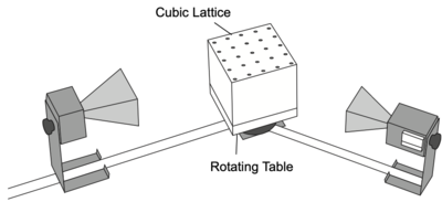
- Adjust the Transmitter and Receiver so that they directly face each other. Align the crystal so that the planes that you want to study are parallel to the incident microwave beam. Note that there are several sets of planes from which you can choose. Adjust the Receiver controls to provide a readable signal. Record the meter reading.
- Rotate the crystal (with the rotating table) one degree clockwise and the Rotatable Goniometer arm two degrees clockwise. Record the grazing angle of the incident beam and the meter reading. (The grazing angle is the complement of the angle of incidence. It is measured with respect to the plane under investigation, not the face of the cube).
- Continue in this manner, rotating the Goniometer arm two degrees for every one-degree rotation of the crystal. Record the angle and meter reading at each position.
- Use your data, the known wavelength of the microwave radiation ($\lambda = 2.85\,\mathrm{cm}$), and Bragg’s Law to determine the spacing between the planes of the Bragg Crystal. Measure the spacing between the planes directly, and compare it with your experimental determination.

Results & analysis
The results of the measurement are shown in Figure 3 (note the error bars!).

We can identify clearly six peaks at $12^{\circ}$, $20^{\circ}$, $24^{\circ}$, $31^{\circ}$, $47^{\circ}$ and $59^{\circ}$. Considering that the wavelength of the source used to measure the diffraction is $\lambda=2.85\,\mathrm{cm}$, we use Bragg's law to obtain the following values for the interplane distance $d$:
| Peak position ($^{\circ}$) | Diffraction order ($n$) | $d$ |
|---|---|---|
| 12 | 1 | (6.12 $\pm$ 0.25) |
| 20 | 1 | (3.77 $\pm$ 0.09) |
| 24 | 1 | (3.17 $\pm$ 0.06) |
| 31 | 1 | (2.50 $\pm$ 0.03) |
| 47 | 2 | (3.53 $\pm$ 0.03) |
| 59 | 2 | (3.01 $\pm$ 0.02) |
The actual separation between planes is $(3.80 \pm 0.05)\,\mathrm{cm}$, from which we can conclude that the peaks at 20$^{\circ}$ and at 47$^{\circ}$ correspond to the first and second diffraction orders of the planes. The other peaks, therefore, must be due to reflections with other planes of the crystal.